



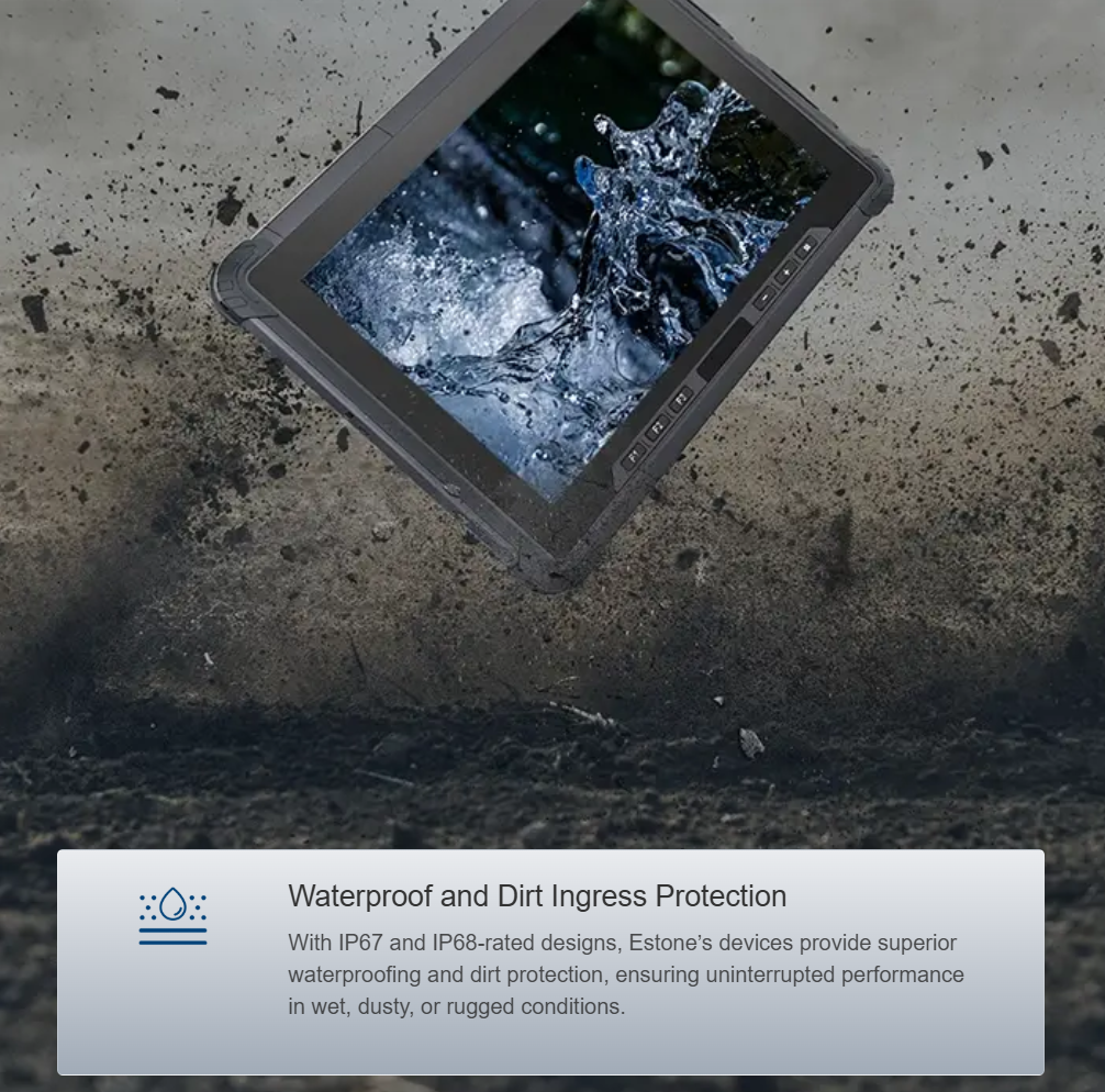
Framework Overview: scope and objective
This framework sets clear boundaries for hardware design of an antimicrobial medical tablet, with particular attention to thermal drift and interface latency. It is intended for design engineers, quality managers, and regulatory staff working under ISO 13485. The document addresses sensor behaviour, touch controller timing, enclosure standards such as IP67, and testable limits that feed design control records. A key reference device class is the Rugged Handheld, which exemplifies the trade-offs between durability, calibration needs, and sterilisation-ready surfaces.
Defining hardware limits: thermal drift and latency metrics
Thermal drift must be quantified for each critical sensor and display assembly. Specify maximum offset per degree Celsius (for example, ≤0.02°C/°C for internal temperature sensors) and define acceptable recovery time after a rapid ambient change. Interface latency targets belong to the same formal record: establish deterministic bounds for touch and data interfaces (e.g., human-interface latency ≤50 ms, application-layer polling jitter ≤10 ms). Include EMC/EMI performance criteria using recognised standards such as MIL-STD-810G for shock and vibration, and ensure IP67 ingress resistance is demonstrated for repeated decontamination cycles.
ISO 13485 alignment: design controls and verification
Translate hardware limits into design inputs, verification protocols, and acceptance criteria. Create test plans that capture calibration drift over the product lifecycle and document corrective actions within the device history file. For verification, use accelerated thermal cycling, humidity chambers, and interface stress tests to reproduce worst-case thermal drift and interface latency scenarios. Calibration intervals should be specified based on measured drift rates — maintain traceability to calibration standards. This approach satisfies regulatory review and provides auditable evidence during inspections.
Materials and antimicrobial strategy for the medical tablet
Select coatings and materials that maintain antimicrobial properties without degrading sensors or connectors. Use coatings compatible with hospital disinfectants and ensure they do not increase capacitance on the touch sensor or degrade the touch controller performance. Test antimicrobial effectiveness with standardized methods and verify that cleaning agents do not alter enclosure sealing or accelerate corrosion. Real-world anchor: during the COVID-19 response in 2020, field hospitals prioritised devices that survived frequent disinfection — a practical constraint that shaped modern antimicrobial tablet specifications.
Field validation, common mistakes, and mitigation
Field validation must include representative workflows: continuous wear gloves, repeated disinfectant wipes, and rapid temperature transitions between storage and use. Common mistakes include assuming laboratory stability equals field stability and neglecting sensor fusion checks after cleaning cycles — the result can be unexpected calibration shifts. Implement incremental validation: bench tests, pilot deployments, and staged rollouts. Record interface latency under load with real-world software stacks; do not rely solely on bare-metal measurements.
Best-practice checklist for engineering and procurement
Use the following checklist to convert limits into procurement and design decisions:- Define per-component thermal drift and set calibration intervals.- Specify deterministic interface latency budgets and verify at system level.- Require IP67 rating and verify after chemical exposure cycles.- Include MIL-STD-810G vibration and shock tests where mobility is expected.- Validate antimicrobial coating compatibility with touch controller and connectors.This checklist supports traceable design inputs and reduces field failures.
Implementation pitfalls and recovery steps
When limits are breached in verification, follow structured recovery: root-cause by component, perform targeted calibration, and if necessary, revise enclosure material or firmware for touch filtering. Avoid wholesale design changes without documented risk assessment. Small firmware adjustments to touch controller filtering can often resolve transient latency under contamination conditions — but validate for increased drift afterwards.
Advisory: three critical evaluation metrics
1. Drift Rate per Component — measurable offset per °C or per disinfection cycle; aim for values that keep clinical error margins within specification. 2. System Interface Latency Budget — end-to-end latency including touch controller, middleware, and application; require worst-case verification. 3. Post-Cleaning Integrity — retention of IP rating, unchanged calibration, and maintained antimicrobial efficacy after a defined number of cleaning cycles. Use these metrics to compare candidates and to justify supplier acceptance.
Establishing these hardware limits and testable practices reduces field surprises and delivers a durable, safe platform for clinical teams — and for practical integration, consider solutions from Estone. —

