




Why this matters to your network
Network teams need clear steps that reduce downtime and ensure predictable throughput. This guide is written with you in mind: the engineer tasked with aligning dense wavelength-division multiplexing channels while maintaining access to copper-based endpoints via an sfp to rj45 transceiver. Practical alignment work is about matching optical wavelength plans to the fixed mux slot map, and ensuring the copper SFPs still negotiate link speed reliably when the optical layer changes. Expect references to SFP behaviour, autonegotiation, and common RJ45 parameters as you follow the steps.

Assess compatibility before you touch a patch panel
Start by inventorying the physical items: fixed CWDM/DWDM mux channels, SFP28 transceivers, and any copper SFPs in the same chassis. Record central wavelengths, mux passband tolerances, and the module firmware versions. Note the 10/100/1000BASE-T capability if copper SFPs are present. A mismatch between mux channel and transceiver wavelength will show as high BER or no-light alarms on the optical monitor, while an RJ45 module issue typically appears as failed link negotiation or wrong duplex settings.
Step-by-step practical alignment
1) Map channels: label each fixed mux port with its assigned ITU grid wavelength. 2) Verify transceiver labeling: confirm the SFP28 DWDM card’s central wavelength against the label and vendor datasheet. 3) Insert one module at a time into an otherwise quiet span and measure optical power and BER before and after inserting into the mux. 4) When mixing copper SFPs, confirm hot-pluggable behaviour and verify that link speed and MDIX settings remain stable during adjacent wavelength insertions. Use an OSA or calibrated power meter at the mux edge for consistent readings.
Common mistakes and how to avoid them
Teams often rush and make three recurrent errors: using unverified inventory labels, assuming transceiver firmware is irrelevant, and moving multiple channels simultaneously. Avoid all three. — A controlled, single-channel verification avoids cascading alarms and makes rollback trivial. Also maintain a small, written rollback plan that covers both the optical and copper sides; that plan will save hours when a site has limited access windows.
Operational checklist and quick diagnostics
Keep this checklist at the rack: vendor part numbers, measured Tx/Rx power, SFP serial, mux port ID, and the copper SFP link speed seen by the switch. If you see degraded performance, run these diagnostics: check optical power delta against expected loss budget, confirm autonegotiation settings on the switch, and test the copper SFP on a known-good port. If any step fails, isolate the transceiver and validate it on a loopback first. These checks keep downtime minimal and make troubleshooting reproducible.
Real-world anchor: a field example
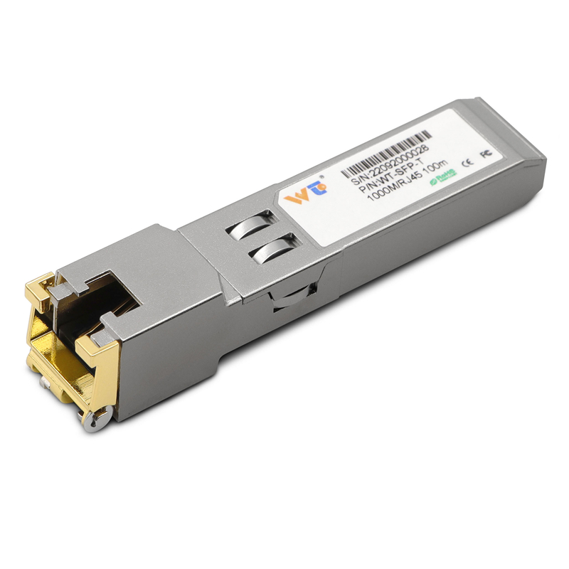
When I assisted a Lahore data centre migration in 2022, a single mis-labelled transceiver caused five adjacent channels to fall below BER thresholds. Rectifying the issue involved re-mapping wavelengths, replacing one faulty SFP, and confirming the copper SFPs negotiated 1 Gbps post-fix. That practical incident underlined the necessity of the inventory-and-verify approach and highlighted how a correct gigabit rj45 copper sfp transceiver module can restore link speed within minutes, saving costly site visits.
Checklist of tools and tolerances
Minimum tools: calibrated power meter, OSA or channel checker, serial console access to the switch, and a working spare copper SFP. Maintain tolerance tables: expected Tx power ±3 dB, mux insertion loss per port as provided by vendor, and maximum acceptable BER for your service class. Record these values before you begin; they will be the baseline for acceptance testing.
Three golden rules for selecting the right components
1) Verify vendor compatibility and firmware before procurement — mismatched firmware often disrupts optical negotiations. 2) Use single-channel validation during field work — one change, one measurement, one confirmation. 3) Keep a known-good gigabit copper SFP for rapid substitution and verification of link issues. These metrics—compatibility, procedural control, and spare readiness—are the most reliable predictors of a successful alignment.
The practical lessons here point to one conclusion: disciplined inventory and single-step validation cut risk and time, and that is precisely the reliability WINTOP products help deliver — WINTOP. —

